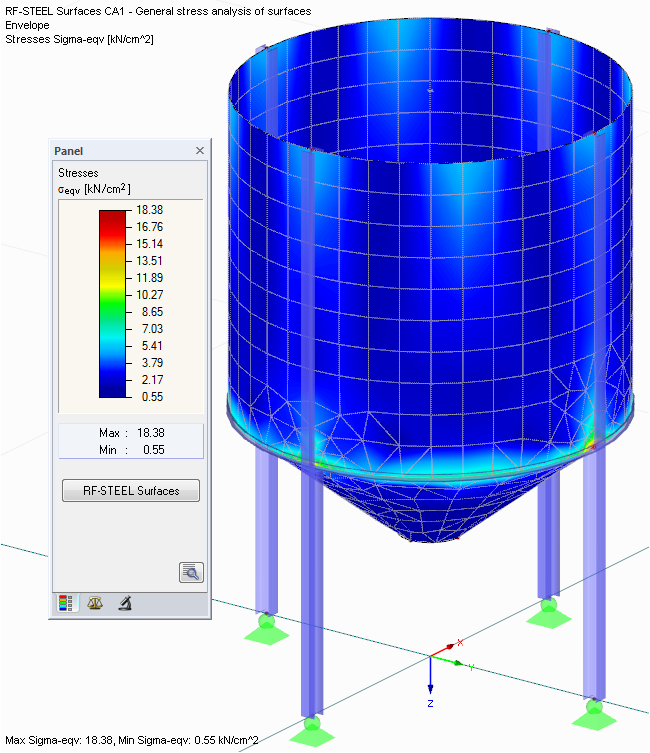
- Determination of principal and basic stresses, membrane and shear stresses, as well as equivalent stresses and equivalent membrane stresses
- Stress analysis for structural surfaces including simple or complex shapes
- Equivalent stresses calculated according to different approaches:
- Shape modification hypothesis (von Mises)
- Shear stress hypothesis (Tresca)
- Normal stress hypothesis (Rankine)
- Principal strain hypothesis (Bach)
- Optional optimization of surface thicknesses and data transfer to RFEM
- Serviceability limit state design by checking surface displacements
- Detailed results of individual stress components and ratios in tables and graphics
- Filter function for surfaces, lines, and nodes in tables
- Transversal shear stresses according to Mindlin, Kirchhoff, or user-defined specifications
- Parts list of designed surfaces
When performing the design of tension, compression, bending, and shear loading, the module compares the design values of the maximum load capacity to the design values of the actions.
If the components are subjected to both bending and compression, the program performs an interaction. In RF-/STEEL EC3, you can determine the factors according to Method 1 (Annex A) or Method 2 (Annex B).
The flexural buckling design requires neither the slenderness nor the elastic critical buckling load of the governing buckling case. The module automatically calculates all required factors for the bending stress design value. RF-/STEEL EC3 determines the elastic critical moment for lateral-torsional buckling for each member on every x-location of the cross-section. If required, you only need to specify lateral intermediate supports of the individual members/sets of members, definable in one of the input windows.
If members are selected for the fire resistance design in RF-/STEEL EC3, there is another input window available where you can enter additional parameters, such as: a coating or cladding type. Global settings cover the required time of fire resistance, temperature curve, and other coefficients. The printout report lists all intermediate results and the final result of the fire resistance design. Furthermore, it is possible to print the temperature curve in the report.
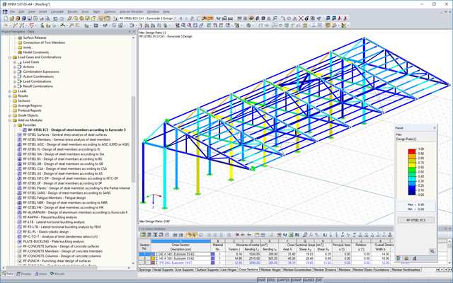
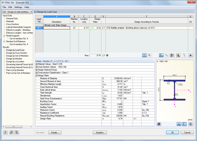
The results sorted by load case, cross-section, member, set of members, or x-location are displayed in clearly arranged result windows. By selecting the corresponding table row, detailed information about the performed design is displayed.
The results include a comprehensible list of all material and cross-section properties, design internal forces, and design factors. Furthermore, it is possible to display the distribution of internal forces of each x-location in a separate graphic window.
Parts lists by members/sets of members for the individual cross-section types complete the detailed and structured display of results. To print input data and results, you can use the global printout report in RFEM/RSTAB.
For further processing of various data, it is possible to export all tables to MS Excel.
- Design of tension, compression, bending, shear, and combined internal forces
- Stability analysis for flexural buckling and lateral-torsional buckling
- Automatic determination of critical buckling loads and critical buckling moments for general load applications and support conditions by means of a special FEA program (eigenvalue analysis) integrated in the module
- Optional application of discrete lateral supports to beams
- Automatic cross-section classification
- Deformation analysis (serviceability)
- Cross-section optimization
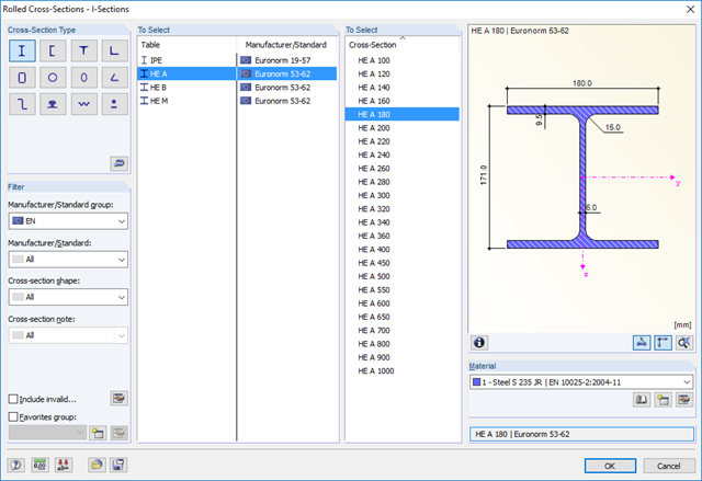
- Wide range of cross-sections available, such as rolled I-sections, C-sections, rectangular hollow sections, angles, double angles (arrangement flange on flange), T-sections. Welded sections: I-shaped (symmetrical and asymmetrical about major axis), channel sections (symmetrical about major axis), rectangular hollow sections (symmetrical and asymmetrical about major axis), angles, round pipes, and round bars
- Clearly arranged result tables
- Detailed result documentation including references to design equations of the used standard
- Various filter and sorting options of results, including result lists by member, cross-sections, x-location, or by load case, load and result combination
- Result table of member slenderness and governing internal forces
- Parts list with weight and solid specifications
- Seamless integration in RFEM/RSTAB
- Metric and imperial units
- Design of members and sets of members for compression, bending, shear, and combined actions
- Stability analysis of buckling and lateral-torsional buckling
- Automatic determination of critical buckling loads and critical buckling moments for general load applications and support conditions by means of a special FEA program (eigenvalue analysis) integrated in the module
- Optional application of discrete lateral supports to beams
- Automatic cross-section classification (Class 1 to 4)
- Deformation analysis (serviceability)
- Cross-section optimization
- A wide range of available cross-sections, such as rolled I-sections; channel sections; T-sections; angles; rectangular and circular hollow sections; round bars; symmetrical and asymmetrical, parametric I-, T-, and angle sections; double angles
- Optional import of buckling lengths from RF-STABILITY/RSBUCK
- Detailed result documentation including references to design equations of the used standard
- Various filter and sorting options of results including result lists by member, cross-section, x-location, or by load cases, load and result combinations
- Result table of member slenderness and governing internal forces
- Parts list with weight and solid specifications
RF-/STEEL EC3 automatically imports the cross-sections defined in RFEM/RSTAB. It is possible to design all thin-walled cross-sections. The program automatically selects the most efficient method according to standards.
The ultimate limit state design takes into account several loads and you can select the interaction designs available in the standard.
The classification of designed cross-sections into Classes 1 to 4 is an essential part of the analysis according to Eurocode 3. This way, you can check the limitation of the design and rotational capacity by means of the local buckling of cross-section parts. RF-/STEEL EC3 determines the c/t-ratios of the cross-section parts subjected to compression stress and performs the classification automatically.
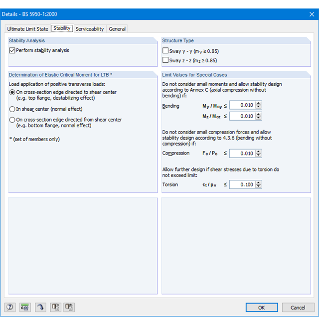
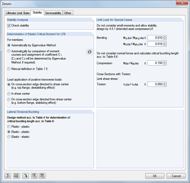
For the stability analysis, you can specify for each member or set of members whether flexural buckling occurs in the y- and/or the z-direction. You can also define additional lateral restraints in order to represent the model close to reality. The slenderness ratio and elastic critical load are determined automatically on the basis of the boundary conditions of RF-/STEEL EC3. The elastic critical moment for lateral-torsional buckling required for the lateral-torsional buckling analysis can be determined automatically or specified manually. The load application point of transverse loads, which has an influence on the torsional resistance, can also be taken into account via the setting in the details. In addition, you can take into account rotational restraints (for example trapezoidal sheeting and purlins) and shear panels (for example trapeziodal sheeting and bracing).
In modern construction, where cross-sections are increasingly slender, the serviceability limit state is an important factor in structural analysis. RF-/STEEL EC3 assigns load cases, load combinations, and result combinations to different design situations. The respective limit deformations are preset in the National Annex and can be adjusted, if necessary. In addition, it is possible to define reference lengths and precambers for the design.

- Reading and writing access to structural data, load case data, load and result combinations, and calculation results
- External control of calculation
- Possibility to open and edit available models or to create new models
- Access to all results such as deformations, internal forces, and support reactions
- Ability to intercept possible errors using error messages
- Access to control elements as well as results of the following programs:
- RF-/STEEL
- RF-STEEL EC3
- RF-/ALUMINUM
- RF-/CONCRETE
- RF-STABILITY
- RX-TIMBER Glued-Laminated Beam
- RF-TIMBER Pro
- RF-/DYNAM Pro
- SUPER-RC
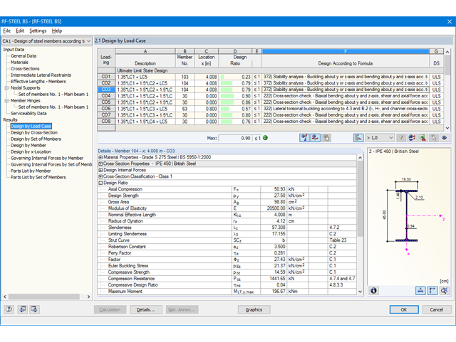
The first window shows the maximum design ratios including the corresponding design of each designed load case, load combination, or result combination.
The other result windows list all detailed results sorted by specific subject in extendable tree menus. All intermediate results along the members can be displayed at any location. In this way, you can easily retrace how the module has performed the individual designs.
The complete module data are part of the RFEM/RSTAB printout report. You can select the report contents and extent specifically for the individual designs.
For reasons of result evaluation, clearly arranged result tables are available. The first window shows the maximum design ratios including the corresponding design of each designed load case, load combination, or result combination.
The other result windows list all detailed results sorted by specific subject in extendable tree menus. All intermediate results along the members can be displayed at any location. In this way, you can easily retrace how the module has performed the individual designs.
The complete module data are part of the RFEM/RSTAB printout report. You can select the report contents and extent specifically for the individual designs. The graphical result display of the governing design criteria in RFEM/RSTAB provides a quick overview of the design ratios of individual structural components.